At the very beginning of the 20th century, the outstanding inventor of Serbian origin, Nikola Tesla, worked on a wireless option for power transmission, but even after a century such developments did not receive large-scale industrial applications. The main way to deliver energy to the consumer is still cable and overhead power lines.
Power Lines: purpose and types
The power line is perhaps the most basic component of electric networks, which is part of the system of power equipment and devices, the main purpose of which is to transfer electric energy from plants producing it (power plants), converting and distributing (power substations) to consumers. In general cases, this is the name of all electrical lines that are outside of the listed electrical facilities.
Historical note: the first power transmission line (DC, 2 kV) was built in Germany according to the project of the French scientist F. Depreux in 1882. It had a length of about 57 km and connected the cities of Munich and Miesbach.
By the method of installation and arrangement, cable and overhead power lines are separated. In recent years, especially for the energy supply of megacities, gas-insulated lines have been built. They are used to transfer high capacities in conditions of very dense development to save the area occupied by power lines and ensure environmental standards and requirements.
Cable lines find application where the arrangement of air is difficult or impossible by technical or aesthetic parameters. Due to the comparative cheapness, better maintainability (on average, the time to eliminate an accident or malfunction is 12 times less) and high throughput, overhead power lines are most in demand.
Definition General classification
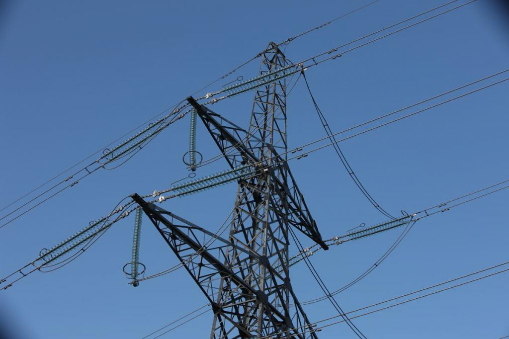
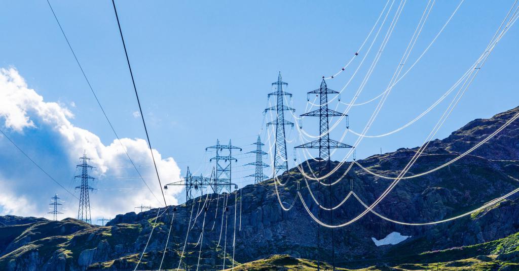
Electric Overhead Line (VLEP) - a set of devices located in the open air and designed to transmit electricity. The structure of overhead lines includes wires, traverses with insulators, supports. As the latter, in some cases, structural elements of bridges, overpasses, buildings and other structures may be used. In the construction and operation of overhead power lines and networks, various auxiliary fittings (lightning protection, grounding devices), additional and related equipment (high-frequency and fiber-optic communications, intermediate power take-offs) and components marking components are also used.
By the nature of the transmitted energy, overhead lines are divided into AC and DC networks. The latter, due to certain technical difficulties and inefficiencies, are not widespread and are used only for power supply to specialized consumers: direct current drives, electrolysis shops, city contact networks (electrified vehicles).
According to the rated voltage, overhead power lines are usually divided into two large classes:
- Low voltage, voltage up to 1 kV. State standards define four nominal values: 40, 220, 380 and 660 V.
- High voltage, over 1 kV. Twelve nominal values are defined here: medium voltage - from 3 to 35 kV, high - from 110 to 220 kV, ultra-high - 330, 500 and 700 kV and ultra-high - over 1 MV.
Note: all the figures given correspond to the interphase (linear) voltage of a three-phase network (six- and twelve-phase systems do not have serious industrial distribution).
From GOELRO to UES
The following classification describes the infrastructure and functionality of overhead power lines.
According to the coverage of the territory of the network are divided:
- ultra-long (voltage over 500 kV), designed to connect regional energy systems;
- trunk (220, 330 kV), serving for their formation (connection of power plants with distribution facilities);
- distribution (35 - 150 kV), the main purpose of which is the supply of electricity to large consumers (industrial facilities, the agricultural complex and large settlements);
- supply or supply (below 20 kV), providing energy supply to other consumers (urban, industrial and agricultural).
Overhead power lines are important in the formation of the Unified Energy System of the country, the foundation of which was laid during the implementation of the GOELRO (State Electrification of Russia) plan of the young Soviet Republic about a century ago to ensure a high level of reliability of energy supply, its fault tolerance.
According to the topological structure and configuration, the high-voltage power lines can be open (radial), closed, with backup (containing two or more sources) power.
By the number of parallel circuits passing along one route, the lines are divided into single, double, and multi-circuit (a circuit means a complete set of wires of a three-phase network). If the circuits have different nominal voltage values, then such a high-voltage line is called combined. Chains can be mounted both on one support, and on different. Naturally, in the first case, the mass, dimensions and complexity of the support increase, but the protection zone of the line decreases, which in densely populated areas sometimes plays a decisive role in the preparation of the project.
Additionally, separation of overhead lines and networks is used, based on the performance of the neutrals (isolated, solidly grounded, etc.) and the operating mode (standard, emergency, installation).
Secured territory
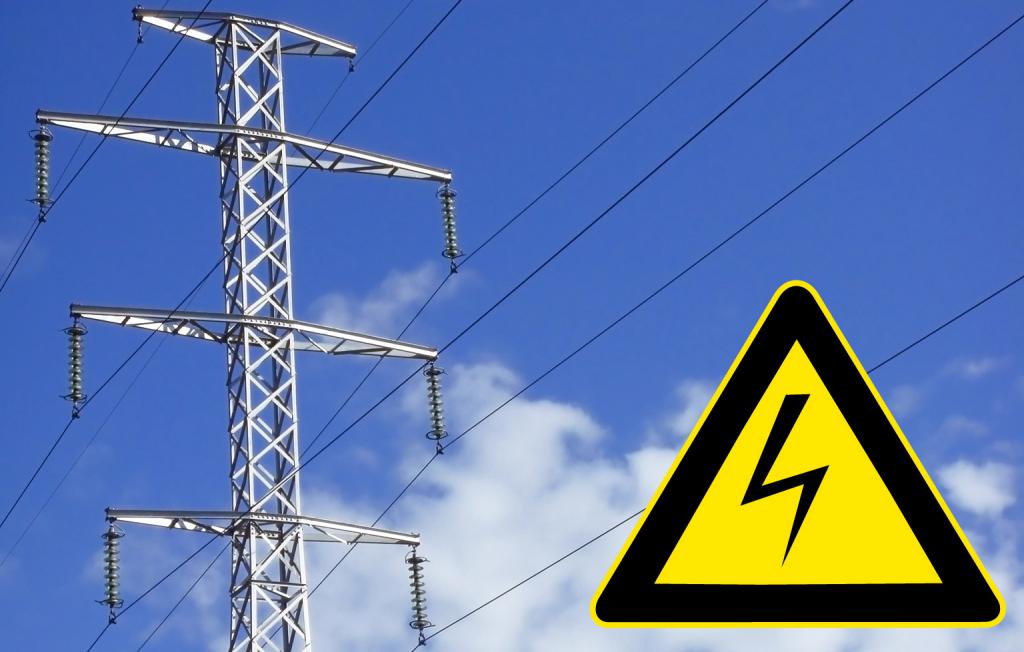
To ensure the safety, normal functioning, ease of maintenance and repair of high-voltage lines, as well as to prevent injuries and deaths, zones with a special mode of use are introduced along the routes. Thus, the security zone of overhead power lines is a land plot and the air space above it, enclosed between vertical planes that are at a certain distance from the outer wires. In the security zones prohibited the work of lifting equipment, the construction of buildings and structures. The minimum distance from the overhead power line is determined by the rated voltage.
| Design voltage, kV | Distance, m |
| up to 1 | 2 |
| from 1 to 20 | 10 (for insulated wires - 5) |
| 35 | 15 |
| 110 | 20 |
| 150; 220 | 25 |
| 330; 500; ± 400 (DCV) | 30 |
| 750 (ACV and DCV) | 40 |
| 1150 | 55 |
When crossing non-navigable water bodies, the protective zone of overhead power transmission lines corresponds to similar distances, and for navigable waters its size increases to 100 meters. In addition, the guidelines determine the smallest removal of wires from the surface of the earth, industrial and residential buildings, trees. It is forbidden to lay high-voltage routes over the roofs of buildings (except for production, in special cases), over the territories of children's institutions, stadiums, cultural and entertainment and trading floors.
Power transmission line pylons
Supports - structures made of wood, reinforced concrete, metal or composite materials to provide the required distance of wires and lightning protection cables from the earth's surface. The most budgetary option - wooden racks, used very widely in the last century in the construction of high-voltage lines - are gradually being decommissioned, and new ones are almost not installed. The main elements of the supports of overhead power lines include:
- foundation foundations
- racks
- struts
- stretch marks.
Designs are divided into anchor and intermediate. The first set at the beginning and end of the line, when changing the direction of the route. A special class of anchor supports is transitional, used at the intersections of the high-voltage power lines with water arteries, overpasses and similar objects. These are the most massive and heavily loaded structures. In difficult cases, their height can reach 300 meters!
The strength and dimensions of the construction of the intermediate supports, used only for straight sections of tracks, are not so impressive. Depending on the purpose, they are divided into transpositional (used to change the location of phase wires), cross, branch, lowered and increased. Since 1976, all the supports have been strictly unified, but nowadays there is a process of moving away from the mass use of typical products. They try to adapt each track as much as possible to conditions of a relief, landscape and climate.
Wires for overhead power lines
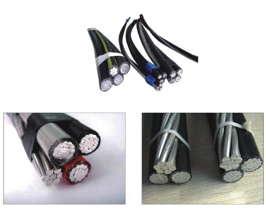
The main requirement for VLEP wires is high mechanical strength. They are divided into two classes - non-insulated and isolated. They can be made in the form of multi-wire and single-wire conductors. The latter, consisting of one copper or steel core, are used only for the construction of low voltage routes.
Stranded wires for overhead power lines can be made of steel, alloys based on aluminum or pure metal, copper (the latter, due to the high cost, on long routes, are practically not used). The most common conductors are made of aluminum (the letter "A" is present in the designation) or steel-aluminum alloys (grade AC or ACS (reinforced)). Structurally, they are twisted steel wires over which aluminum conductors are wound. Steel, for protection against corrosion, galvanized.
The choice of the section is made in accordance with the transmitted power of the allowable voltage drop, mechanical characteristics. Standard cross-sections of wires produced in Russia are 6, 10, 16, 25, 35, 50, 70, 95, 120 and 240. An idea of the minimum cross-sections of wires used for the construction of overhead lines can be obtained from the table below.
| Core material | Lines over 1 kV, mm2 | Lines up to 1 kV, mm2 | Branches to inputs (length up to 10 m / over 10 m), mm2 |
| Copper | 25 | 2,5 | |
| Steel | 25 | 25 | 4/4 |
| Aluminum | 356 | 16 | 6 / 10 |
Branches are performed more often with insulated wires (APR, AVT brands). The products have a weatherproof insulation coating and a steel bearing cable. The wire connections in the spans are mounted in areas not subject to mechanical stress. They are spliced by compression (with the use of appropriate devices and materials) or by welding (with termite blocks or a special apparatus).
In recent years, self-supporting insulated wires are increasingly used in the construction of overhead lines. For low-voltage high-voltage lines, industry produces SIP-1, -2, and -4, and for 10-35 kV lines, SIP-3.
On routes with voltages above 330 kV, to prevent corona discharges, the use of a split phase is practiced - one wire of a large cross section is replaced by several smaller ones, bonded to each other. With an increase in the nominal voltage, their number increases from 2 to 8.
Linear reinforcement
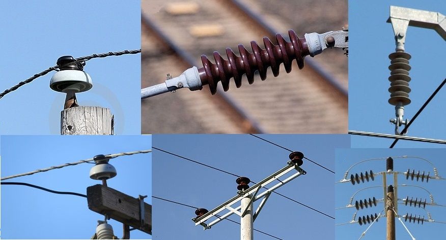
VLEP fittings include traverses, insulators, clamps and suspensions, trims and braces, fasteners (brackets, clamps, hardware).
The main function of the traverse is to fasten the wires in such a way as to provide the necessary distance between the opposite phases. Products are special metal structures made of corners, strip, pins, etc. with a painted or galvanized surface. There are about two dozen sizes and types of traverses, weighing from 10 to 50 kg (designated as TM-1 ... TM22).
Insulators are used for reliable and safe fastening of wires.They are divided into groups, depending on the material of manufacture (porcelain, tempered glass, polymers), functional purpose (support, passage, introductory) and methods of attachment to traverses (pin, rod and pendant). Insulators are made under a certain voltage, which must be indicated in the alphanumeric marking. The main requirements for this type of fittings when installing overhead power lines are mechanical and electrical strength, heat resistance.
To reduce line vibration and prevent breaks in wire wires, special damping devices or damping loops are used.
Technical specifications and protection
When designing and installing overhead power lines, the following important characteristics are taken into account:
- The length of the intermediate span (the distance between the axes of adjacent racks).
- The distance between the phase conductors and the lowest one is from the ground surface (line dimension).
- The length of the string of insulators according to the rated voltage.
- The full height of the supports.
You can get an idea of the main parameters of overhead power lines of 10 kV and above from the table.
| 10 kV | 35 kV | 110 kV | 220 kV | 330 kV | 500 kV | 750 kV | |
| Span, m | up to 150 | 150- 200 | 170-250 | 250-350 | 300-400 | 350-450 | 350-540 |
| Interphase distance, m | 1,0 | 3,0 | 4,0 | 6,6 | 9 | 12 | 17,5 |
| Line dimension, m | 6 | 6,5 | 7 | 7,5 | 7,6-8 | 15,5 | 23 |
| Garland length, m | - | 0,7-1,1 | 1,4-1,7 | 2,3-2,7 | 3,1-3,6 | 4,6-5,1 | 6,8-7,9 |
| Support height, m | 13-14 | 10-21 | 13-31 | 22-41 | 25-43 | 27-32 | 38-41 |
To prevent damage to overhead lines and prevent emergency shutdowns during a thunderstorm, a steel or steel-aluminum cable lightning rod with a cross section of 50-70 mm is launched over phase wires2earthed on poles. Often it is hollow, and this space is used to organize high-frequency communication channels.
Protection against surge arising from lightning strikes is provided by valve arresters. In the event of an induced lightning impulse arising on the wires, a breakdown of the spark gap occurs, as a result of which the discharge flows onto a support having ground potential without damaging the insulation. The resistance of the support is reduced using special grounding devices.
Preparation and installation
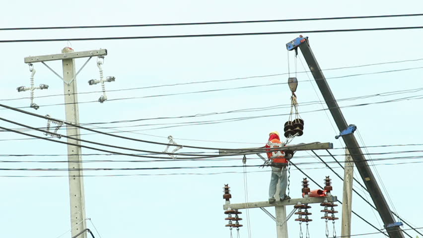
The technological process of construction of the high-voltage power line consists of preparatory, construction and installation and start-up works. The first includes the purchase of equipment and materials, reinforced concrete and metal structures, the study of the project, the preparation of the route and the picket, the development of the PER (plan for the production of electrical work).
Construction work includes digging pits, installing and assembling supports, distributing reinforcement and grounding kits along the route. Directly installing overhead power lines begins with rolling the wires and cables, making connections. Then follows their rise to the supports, tension, sighting of the arrows of the sag (the greatest distance between the wire and the straight line connecting its attachment points to the supports). In conclusion, the wires and cables on the insulators are tied.
In addition to general safety measures, work on overhead power lines imply compliance with the following rules:
- The cessation of all work when approaching a thunderstorm front.
- Ensuring the protection of personnel from the effects of electrical potentials induced in the wires (shorting and grounding).
- Prohibition of night work (except for the installation of intersections with overpasses, railways), ice, fog, with a wind speed of more than 15 m / s.
Before commissioning, check the sag and line dimensions, measure the voltage drop in the connectors, the resistance of the grounding devices.
Service and Repair
According to the work regulations, all overhead lines over 1 kV every six months are subject to inspection by maintenance personnel, engineering and technical personnel - once a year, for the following malfunctions:
- throwing foreign objects onto wires;
- breaks or burnout of individual phase wires, violation of the adjustment of the arrows of the sag (should not exceed the design by more than 5%);
- damage or overlap of insulators, strings, arrester;
- destruction of supports;
- violations in the security zone (storing foreign objects, finding oversized equipment, narrowing the width of the clearing, due to the growth of trees and shrubs).
Extraordinary inspections of the route are carried out during ice formation, during the spill of rivers, natural and man-made fires, as well as after an automatic shutdown. Inspections with a rise on the supports are carried out as needed (at least 1 time in 6 years).
In the event of a violation of the integrity of part of the wire wires (up to 17% of the total cross section), the damaged area is repaired by applying a repair sleeve or bandage. In case of large damage, the wire is cut and reconnected with a special clamp.
During the current repair of the airway, the rickety supports and struts are straightened, the tightness of all threaded joints is checked, the protective paint coat on the metal structures, numbering, signs and posters are restored. Measure the resistance of grounding devices.
Overhaul of overhead power lines implies the performance of all ongoing repairs. In addition, a full hauling of the wires is carried out with the measurement of the transition resistance of the couplings and the carrying out of post-repair test events.